Your cart
There are no more items in your cart
Configure your shade sail online
Design, shape, fabric. Ready in 5 days.
Learn more
Accurate measurement is essential to ensure a quality installation.
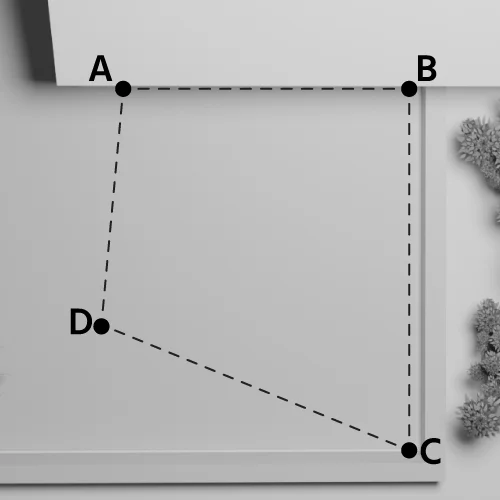
In Phase 1, identify potential anchor points and measure the distances between them.
At this stage, measurements can have a tolerance of a few inches. The final measurements will be confirmed once the anchors are installed.
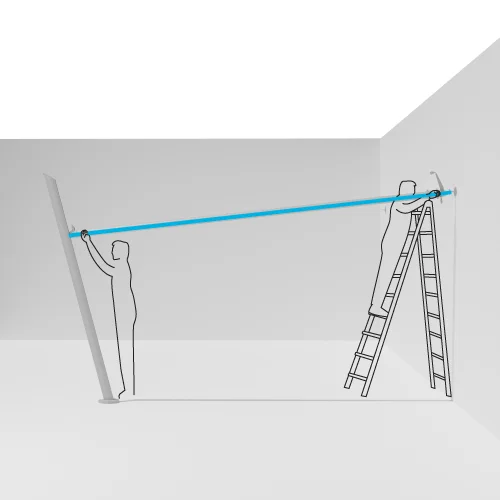
In Phase 2, once the anchors are in place, precise measurements must be taken.
IMPORTANT: All required measurements refer to the anchor points, not the actual fabric dimensions.
The system will automatically calculate the fabric dimensions.
PHASE 1: Use a rigid tape measure to measure the area where you plan to install the sail, considering any obstacles such as walls, trees, or other elements that may affect the installation.
PHASE 2, use the measuring tape provided with the anchor shipment to measure angles and sail diagonals with great precision.
Measurements should always be taken from anchor point to anchor point.
IMPORTANT: If you decide to install the sail with an inclined winding roller, the actual distance between point A and point C will be greater than in a perfectly horizontal installation. This happens because tilting the roller increases its length compared to a parallel ground installation.
The AC side is conventionally referred to as the roller tube side.
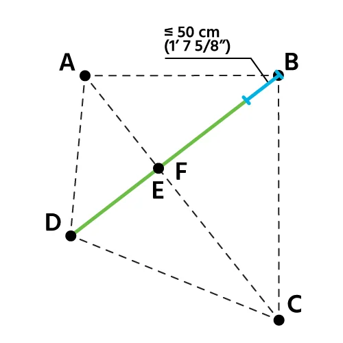
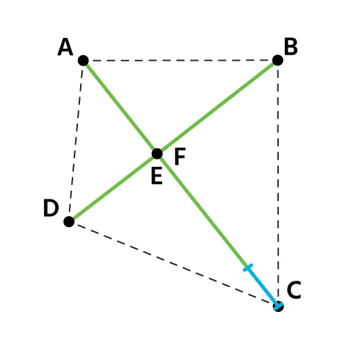
In a quadrilateral (four-cornered sail), AC corresponds to the diagonal.
In a triangle (isosceles, scalene, equilateral), side AC corresponds to one of the sides.
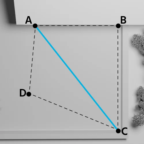
Example: Quadrilateral Shape
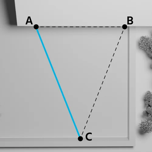
Example: Isosceles, Scalene, Equilateral Triangle
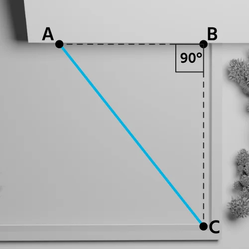
In a right triangle, side AC corresponds to the hypotenuse.
Example: Right Triangle Shape
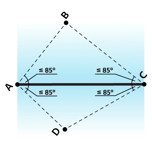
IMPORTANT: See corner constraints for points A and C in the specifications at the bottom of the page.
Angle A is always where the motor is installed, serving as the main reference for configuring the sail.
Defining this corner first allows you to precisely determine the position of other anchor points, ensuring a correct and balanced installation.
Angle A should be the highest point of the boom.
The length of the roller tube (AC side) has a tolerance of 1 inch on each side. This measurement should be taken with great accuracy in PHASE 2, once the anchors are installed.
The roller tube can be inclined.
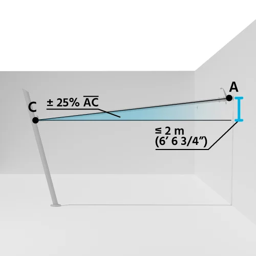
The maximum possible inclination for side AC is ±25% of the roller tube length.
Example:
If the roller tube (AC side) is 26 feet (312 inches) long
Maximum inclination = 312 / 100 x 25 = 78 inches
IMPORTANT: If you install the sail with an inclined roller tube, the actual distance between corner A and corner C will be greater than in a perfectly horizontal installation. This is because tilting the roller increases its length compared to a parallel ground installation.
TIP: We recommend NOT tilting the roller towards corner A, as this is where the motor is.
General Constraints
To ensure project feasibility, it is essential to respect some technical constraints when designing the motorized roll-up sail.
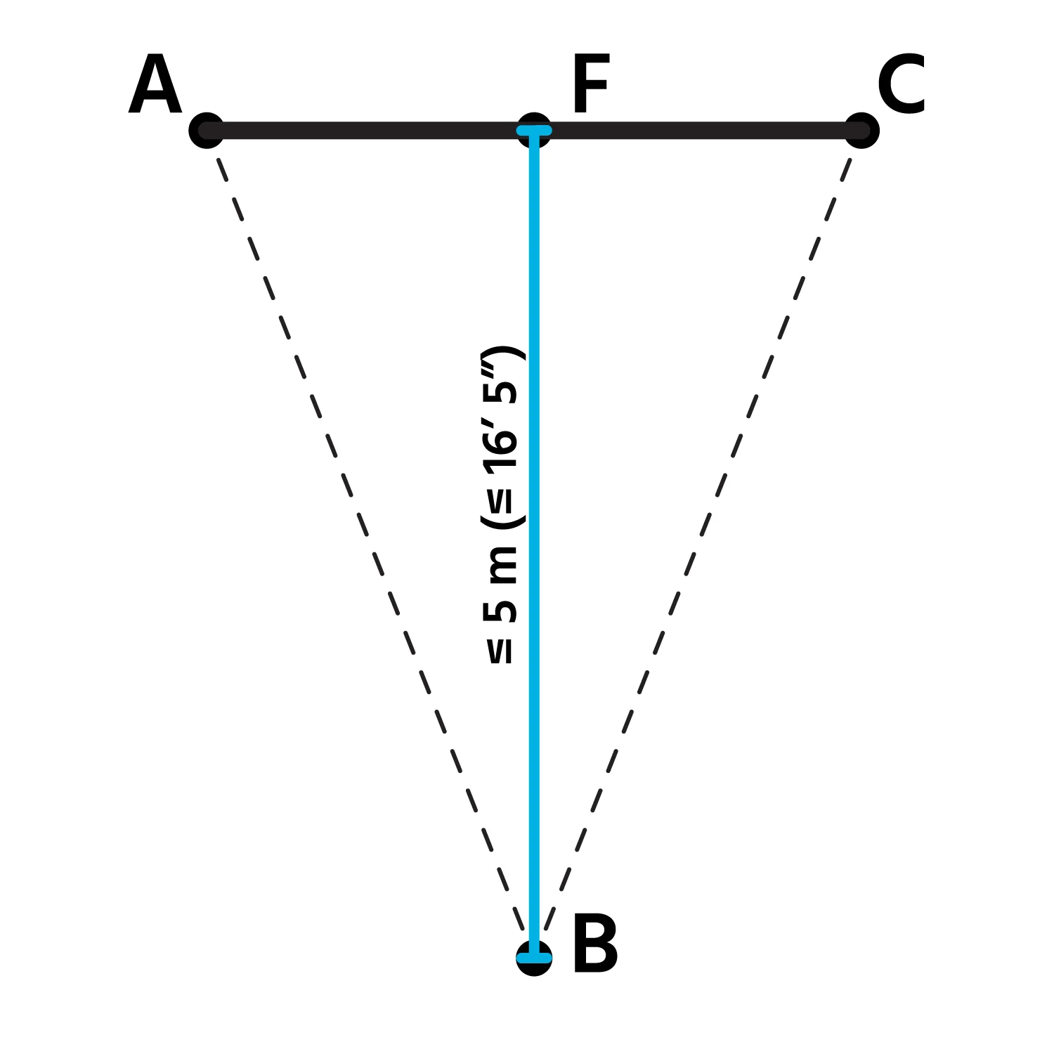
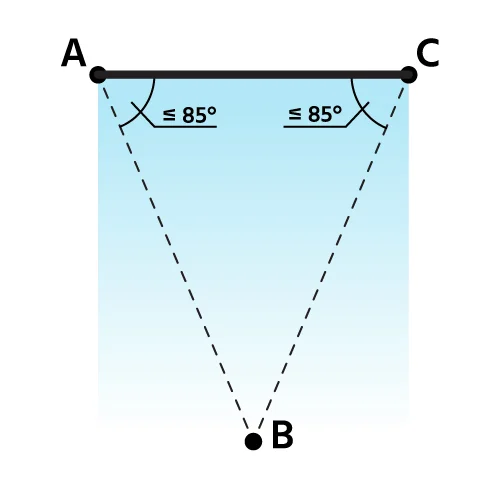
Special Constraints for Triangular Sails
Special Constraints for Quadrilateral Sails


 English (United States)